Getting Started
TALLY-NODE is a system that wirelessly displays camera tally states. This document covers the basic concept of tally, the components of TALLY-NODE, and a quick start flow for first use.
What Is a Tally System?#
Tally is a system used in studios or live events to tell camera operators or on-air talent “which camera is currently on-air” and “which camera is scheduled to go on-air next.”
Types of Tally States#
| State | Meaning | LED color | Operator action |
|---|---|---|---|
| PGM (Program) | Currently on-air | Red | On-air, be careful |
| PVW (Preview) | Scheduled to go on-air next | Green | My turn soon |
| OFF | Not on-air | Off (or blue) | Standing by |
How TALLY-NODE Works#
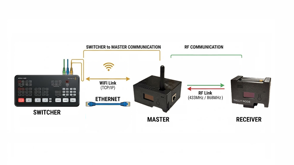
The Master (transmitter) receives tally information from the switcher and broadcasts it over LoRa wireless to every Receiver. Each Receiver displays only the state that corresponds to its own camera_id.
The system is built on two links that use different media.
- Switcher → Master: connected over Ethernet or WiFi. The Master uses this path to receive the switcher's PGM/PVW state, and the operator reaches the Master Web UI over the same network.
- Master → Receiver: a dedicated LoRa wireless (868 MHz or 433 MHz) link. It is a separate radio network on a different band than WiFi, used to broadcast the tally state to every Receiver.
Components#
Device Configuration#
| Device | Qty | Role | Web UI |
|---|---|---|---|
| Master | 1 | Switcher connection, LoRa TX, hosts the HTTP server | Yes (port 80) |
| Receiver | 1-20 | Camera-mounted, LED display | No |
| Free edition (v3.2.0+) | 1 (optional) | Switcher connection, standalone phone web tally (no LoRa/receivers) | Yes (port 80) |
Hardware Specs#
Common specs (Master + Receiver)
- Display: front OLED (128x64)
- Wireless: LoRa (868MHz, built-in antenna)
- WiFi: 2.4GHz
- Power / charging: USB-C (5V), built-in 18650 battery
- Buttons: front button, bottom ON/OFF switch, bottom RESET button
- Mounting: bottom 1/4” mount
- Firmware version: 3.2.0
Free edition (optional build, v3.2.0+)
- Board: ESP32-S3-N8R2 (reference build) — 8MB Flash · 2MB PSRAM, no OLED/LED/LoRa required; see the compatibility table in the DIY guide
- Display: smartphone browser at
http://[device-IP]/tally(real-time WebSocket, up to 10 phones) - Role: provides the same tally sources as a standalone Master (OBS/vMix/ATEM/OSEE) without a receiver fleet
Master only
- LAN port: W5500 RJ45 (wired internet/switcher network)
- Network: Ethernet and WiFi can be used simultaneously
Receiver only
- Rear LED: WS2812B ×8 + diffuser (PGM red / PVW green / OFF)
- Front LED: WS2812B ×4 RGB
Quick Start Flow#
The overall setup proceeds in the following order.
- 1Connect power
- 2Connect the Master to the networkA direct LAN cable to your router is recommended (check the IP on the OLED); without a router, join the AP WiFi (password 12345678)
- 3Open the Web UIOpen the Master IP in a browser (http://192.168.4.1 or DHCP-assigned http://device-ip)
- 4Configure switcher integrationSee Switcher Integration for details
- 5Mount the Receiver + assign IDSee Receiver Operation for details
- 6Verify the first tally display
Free edition quick start#
Module-only setups follow the order below. See the DIY guide for step-by-step instructions.
- 1Flash the firmwareInstall with no login at /flash/free (PC · Chrome/Edge, once)
- 2Join the networkAP (TallyNode-XXXX, password 12345678) → 192.168.4.1 → WiFi setup
- 3Switcher setupSee Switcher Integration for details
- 4Check web tally on phonesOpen http://[device-IP]/tally (up to 10)
Minimum Operation Check (3-step test)#
- Power on the Master: connect USB-C power, the boot logo appears on the OLED
- Open the Web UI: open the Master IP in a browser (the IP varies by AP, WiFi, or ETH)
- Power on the Receiver: battery or USB-C connected, check the LED display